Where Should Rebar Lap Splices Go? Beam and Column Placement Rules
Knowing the required lap length for a rebar splice is something you can get from any textbook. Knowing where along a beam or column that splice is actually allowed to sit is a completely different kind of knowledge, and it is the part I see young engineers get wrong far more often. This is the detail that separates someone who memorized a formula from someone who understands why the formula exists.
The Golden Rule: Splice Where Stress Is Low
A lap splice is inherently a weaker point than a continuous bar, because it relies on bond transfer through concrete instead of one uninterrupted piece of steel. That means the whole point of correct detailing is to put that weaker point somewhere the bar is not being asked to do its hardest work. You never want a splice sitting at the location of maximum tension in a member. If you do, you have built in a weak link exactly where the structure needs its strongest connection.
Where This Actually Plays Out: Columns
In a column, vertical bar splices belong in the middle third of the column height, not at the top or bottom ends. The reason is seismic behavior. During an earthquake, the ends of columns are where plastic hinges tend to form, the zones that absorb the most rotation and stress as a structure sways. Placing a splice inside a plastic hinge zone means asking your weakest connection to survive the harshest demand in the entire member. Keep the splice in the quieter middle section instead, where the column is doing far less dramatic work.
Where This Actually Plays Out: Beams
Beams flip the logic around because the stress pattern is different. Top bars in a simply supported beam carry their peak tension near the supports and are least stressed near mid-span, so top bar splices belong at mid-span. Bottom bars work the opposite way, carrying peak tension at mid-span and least tension near the supports, so bottom bar splices belong close to the supports. On top of getting the location right, good detailing also staggers the splices instead of lining them all up at the same cross-section, so you are never creating one plane in the member where every single bar happens to be spliced at once.
Why This Detail Gets Missed on Real Sites
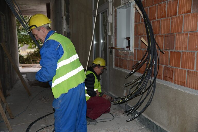
In my experience, this is a detail that lives in the drawings but does not always survive contact with the site. Steel fixers are working with the bar lengths they were delivered, and if a bar happens to run out at an inconvenient point, the temptation is to just lap it wherever the cut lands rather than walking back to the drawing to check whether that location is even acceptable. This is exactly the kind of thing a site engineer has to physically watch for, because it will not show up as an obvious defect. It will look like a perfectly normal splice, in the wrong place, and the structure will carry that mistake silently until it matters.
The Number Comes From a Book. The Location Comes From Understanding.
I tell junior engineers this distinction directly. Lap length is something you look up, and once you know it, it does not change based on judgment. Lap location is something you have to understand, because it depends on reading the stress pattern of the specific member in front of you, whether it is a column or a beam, and whether it is top steel or bottom steel. That understanding is what turns a rule into real engineering, and it is exactly the kind of thing that separates a design that looks correct on paper from one that actually behaves correctly when the ground starts moving.
Watch the Full Video in Urdu
I explained this with diagrams in Urdu for my Instagram audience, since seeing the stress zones marked on a beam and column makes the idea click much faster than reading about it. Watch the full reel embedded above, and follow @teeqiii on Instagram for more rebar detailing breakdowns like this one.
If you are reviewing detailing on an active project and want a second opinion on where your splices should sit, reach out through my contact page.